Pin2dmd build
Info on the diy route of making one is a little scattered so I thought this would be helpful to some. These are instructions for a V4 build in a real pinball machine. You need to know how to do basic soldering and wiring that you probably already know if you own a pinball machine. All project info here: https://pin2dmd.com/. Complete parts list and price comparison to the all in one EVO boards can be found here: https://drive.google.com/file/d/1-c5mDV8FaMiYbmZWTt7WirTRFAlCGGCr/view
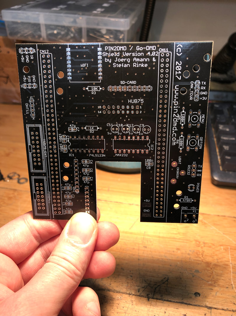
First part needed is the shield, which is just an adapter PCB to connect the Nucleo controller board to the LED screens, power and the signal from your pinball machine plus some buttons to change the menu settings and a slot for a micro SD card that will hold the files to run it. I got mine from elecrow https://www.elecrow.com/pcb-manufacturing.html. You have to upload the v4 gerber files found here: https://github.com/lucky01/PIN2DMD/tree/master/hardware/V4%20NUCLEO-144. Then all you have to change is the dimensions (100mmx100mm), pick a colour, choose HASL no lead and your country and preferred shipping method. Minimum order is 5pcs. If you can solder SMD parts there is another modified version by MikePinball that has a spot for the micro SD card holder and a 10k sip resistor network which will save you a few bucks by not having to order the waveshare card holder. Found here: http://vpuniverse.com/forums/topic/3831-pin2dmd-for-125-diy/
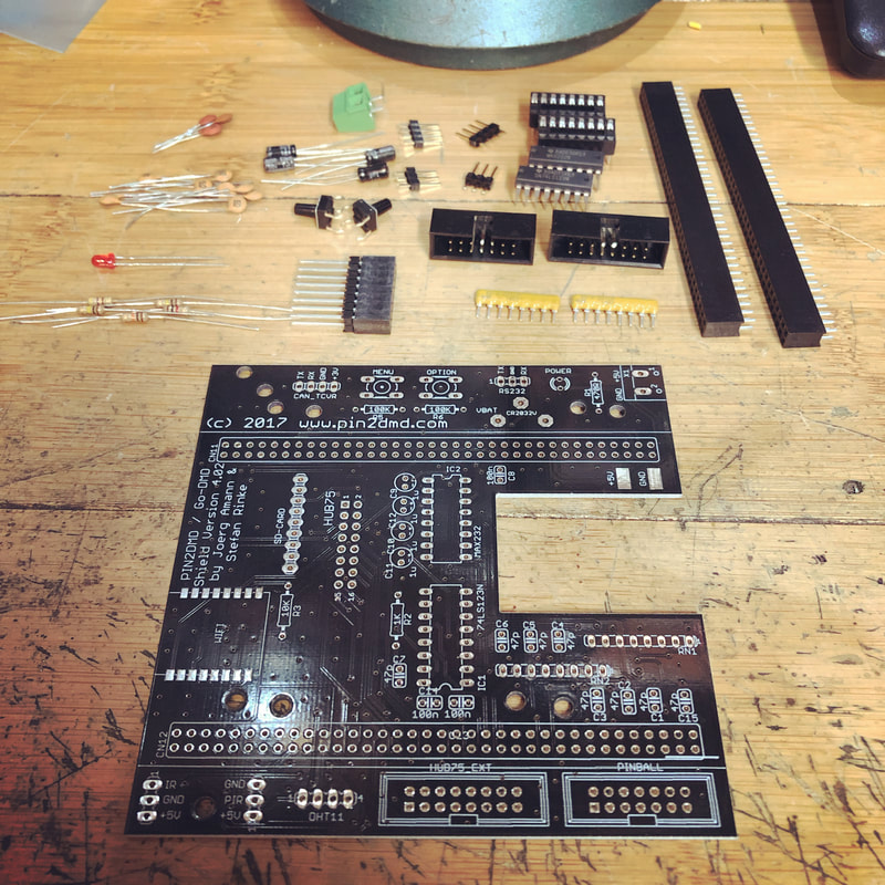
Time to solder. Once you have all your parts, solder away. There are a lot of extras on these boards that I believe are for a goDMD clock that aren't necessary. I left out the battery, wifi, CAN_TCVR, IR, PIR and DHT11 connectors. The sip resistors have a dot at one end that matches the pcb. Same with the box headers and IC sockets, both have notches that should line up with the pictures on the pcb. LED can be any colour. Watch the height on the 1uf caps, get the shortest you can, think the ones I used were 5mmx7mm. Buttons can be any 6x6mm through hole tactile switches that are normally open momentary.
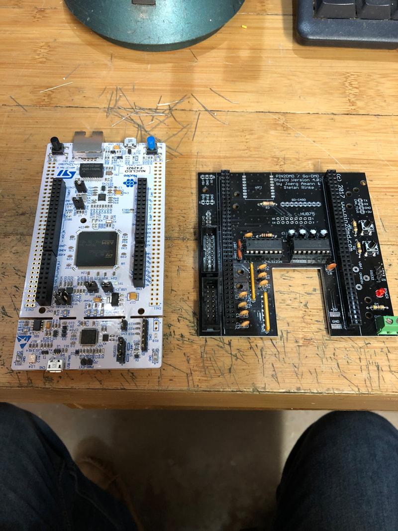
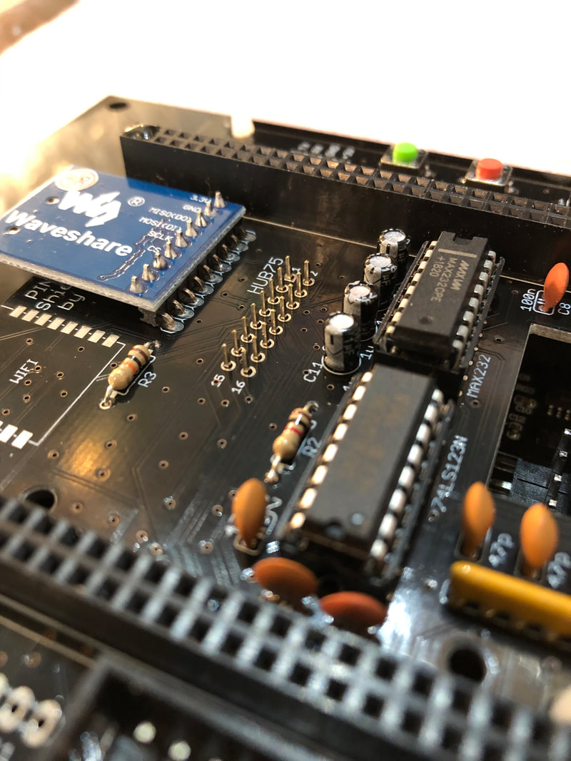
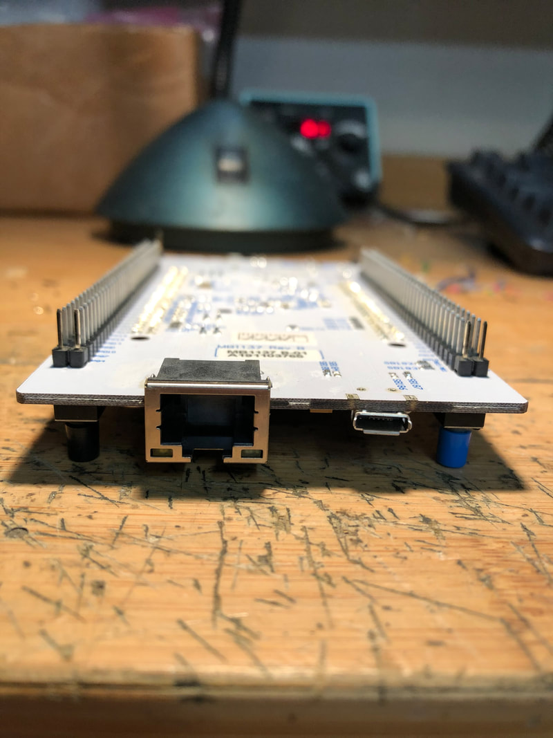
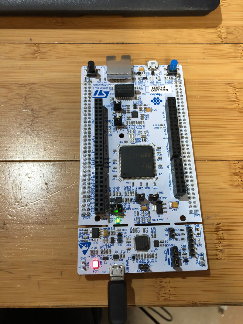
This is what it should look like all soldered up. The Nucleo board is beside for comparison. You can see I've left out the tall stackable header for the HUB75 connection in the middle of the shield. That will get soldered last once you have the LED screens in the frame to set the height properly. I aslo hadn't received the waveshare micro SD card holder yet when I took this pic.
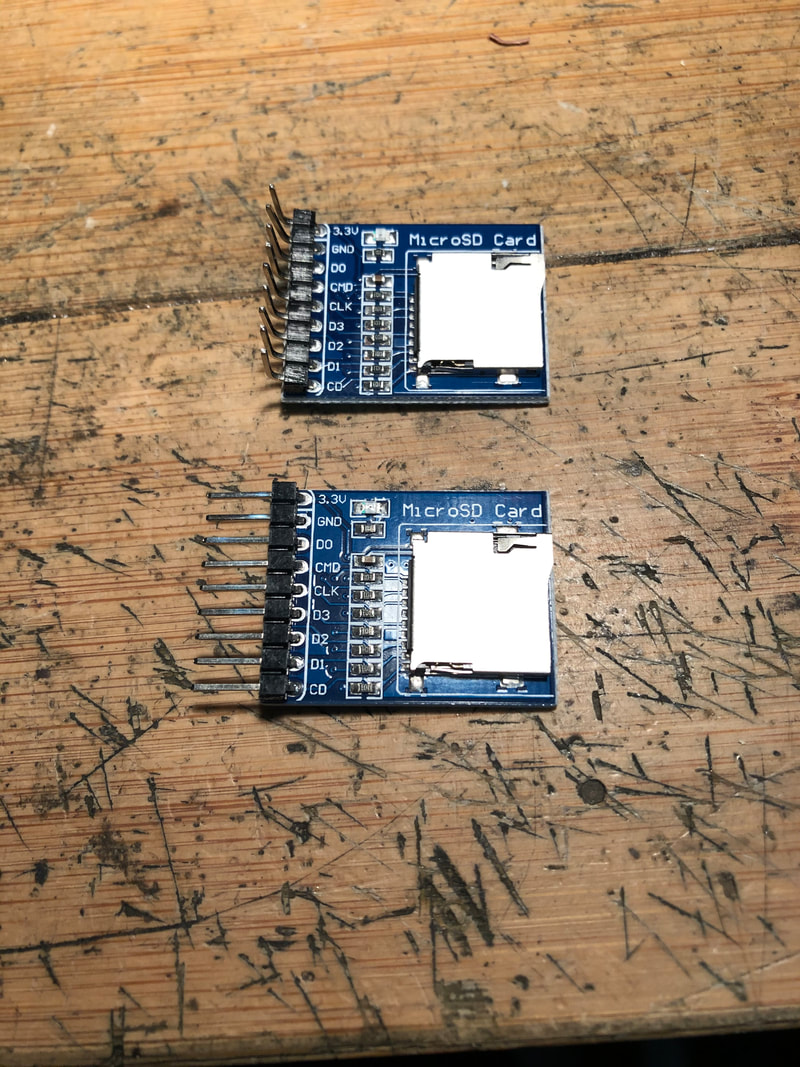
The Waveshare SD card adapters come with straight pins so I just bent them 90 degrees to fit the shield before soldering. Bottom is stock, top is with the bent pins. I put a little piece of double sided foam tape (not shown) on the silver SD card slot top to help adhere it to the circuit board and keep it at an even height as well.

Solder the SD card adapter in as shown in the pic. This pic is also shows how the shield connects to the LED panels and frame. Put a freshly formatted name brand micro SD card in the slot. Format in FAT32 and make sure the card is 32GB or smaller, files you'll put on there are not very big and 1-2GB is tons of space. Cheap Chinese cards are reported to not work well so get a good name brand one. Only files on this card will be the license key, a settings file the unit makes the first time you save your settings, and if your machine has been colourized a PAL file and an FSQ file with the colorization code. All files will be named pin2dmd.key, pin2dmd.dat, etc. Virtual machines use a VNI file instead of an FSQ and a PAL file that's different than the real pin PAL file. Here is a link to all the available colourized files: https://pin-display.ch/files/
or here: https://sites.google.com/view/pin2dmd/colour-files
or here: https://sites.google.com/view/pin2dmd/colour-files
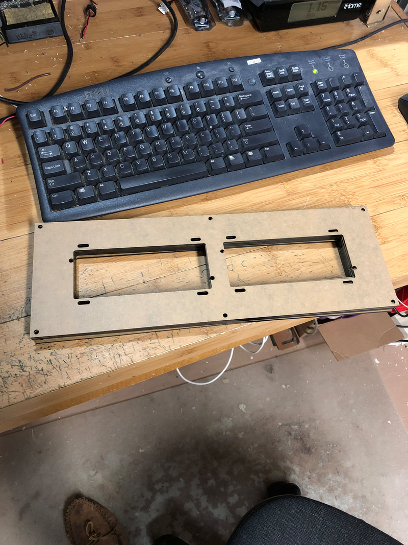
Next piece of the puzzle is the frame to hold it all together. First one I did was a three piece that was 3d printed. Files can be found here: https://www.thingiverse.com/thing:3098697. It works well but laser cut 3mm acrylic panels are the way to go. I had the local College cut some for me based on the .svg file at the bottom of this post: http://vpuniverse.com/forums/topic/2264-frame-for-pin2dmd/page/2/?tab=comments#comment-44627. I've heard ponoko is a good source to get them cut in the USA. DIY is also a possibility with suitable material.
The LED panels you want are p2.5, 160mmx80mm, 64x32 pixel, 1/16 rate, you need two. Can be purchased here: https://www.aliexpress.com/item/4000002686894.html?spm=a2g0s.9042311.0.0.14f44c4ddTwwHe.
Bolt the LED panels to the frame with some 3mm bolts and washers. It's a little tricky to get them lined up with no gap in the middle, so thread the screws almost all the way in and do the final tightening while holding everything straight in the front. Once the panels are securely bolted in and nice and straight, stick the tall 2x8 stackable header in the first LED panel HUB75 socket.

5mm standoffs (I got some from Tayda electronics) are the way to go for attaching the shield to the frame. Here's a bottom shot of the best place to put them. Make sure they're the small footprint ones like these or the mounting screws from the panels will get in the way.
Peel the backing off the little standoffs and put the shield on top with the pins sticking through the holes to be soldered. This is pretty tricky to get lined up, but I found it to be the best way to get the height and position perfect. Solder in place when you get it in and the standoffs are stuck to the frame well.

Make sure to install your HUB75 jumper (grey ribbon cable) from the furthest socket on the same LED panel as the shield to the closest on the next panel, there's nibs in the plugs to help line it up the right way. Also plug the power cable in to both panels before continuing. You can see here how I spliced extra 18G wires onto the existing panel wires to power the shield. The larger panel wires get connected to the 4.8v side of the power converter. Both the shield and LED panels receive the same 4.8v from the power converter.
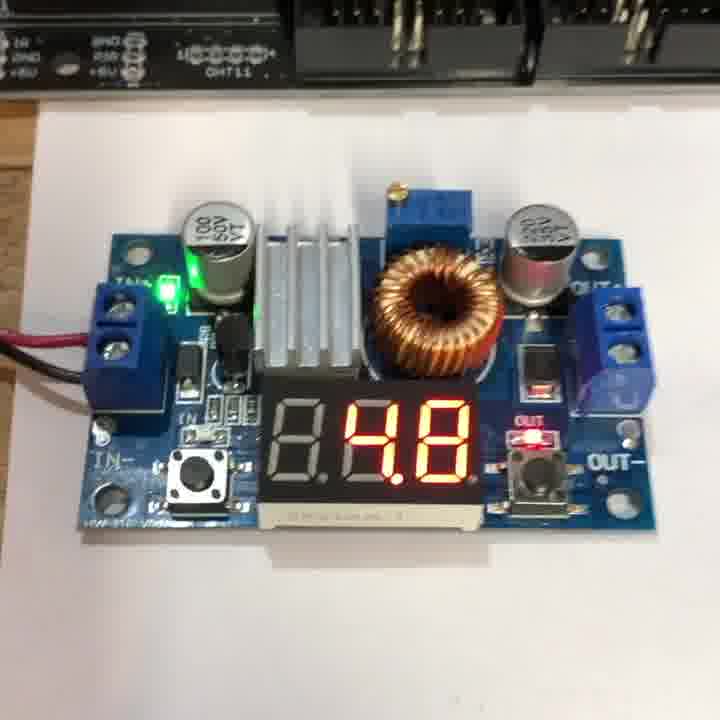
Here's the power converter that needs to be attached on the far side of the frame next. I typically use a brass 5mm tall standoff with 3mm screw threads in one of the bolt holes for the LED panels along with a sticky plastic standoff on the other side of the supply to hold it on. 12vDC on the 'in' side from your machine, adjustable voltage on the 'out' side set to 4.8vDC with the little trim pot at the top. It's a 25 turn one, so you have to crank it down quite a few times to get 4.8v. Double check with a multi-meter that the voltage is correct before connecting to the screens and Nucleo. Any 5A or larger DC/DC converter is good, there's several variations. Ebay is the best bet for these, I got the fancy one with a display: https://www.ebay.ca/itm/5A-Adjustable-Power-DC-DC-Step-down-Charge-Module-LED-Driver-With-Voltmeter/400985379067?ssPageName=STRK%3AMEBIDX%3AIT&_trksid=p2060353.m1438.l2649. I powered mine with a 12vDC computer power supply while testing. Red is positive, black is ground or negative.
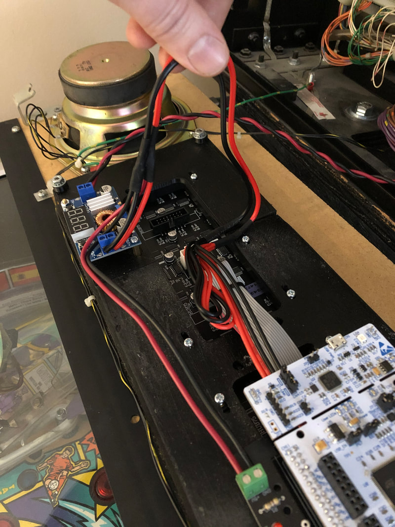
Here's a shot of the output side of the power converter after attaching to the frame. The screens come with a nice long wire that's already split to the two power plugs on the LED screens. I did the same thing on the other end and just split it by soldering another little length of wire on each of the black and red wires. The out now goes to both the LED screens and the connector on the shield pcb. The heat shrink near my fingers is where I split it.
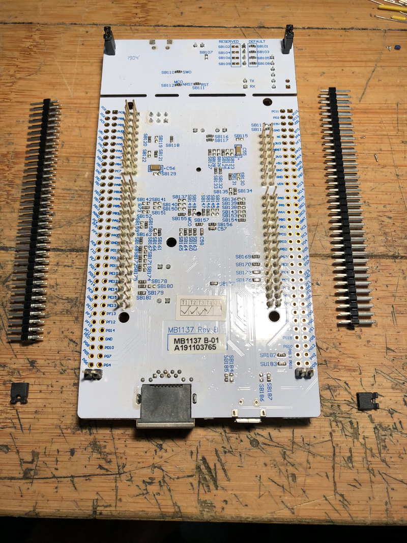
The Nucleo board is next. You have to solder two rows of 35x2 2.54mm pin headers to the bottom of the board. You also have to cut off all the gold pins that are already on there since they'll get in the way of the other stuff on the shield and cause shorts. There's already two pins at the end of each row where you're soldering.
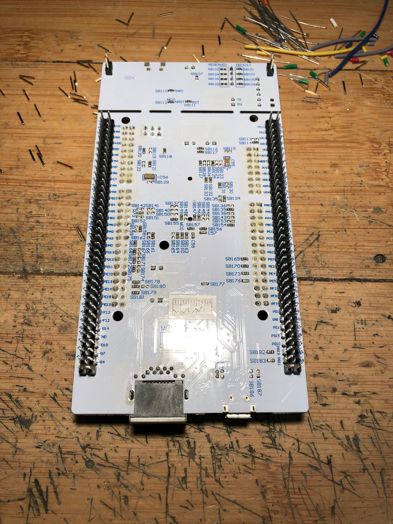
Here is the board after soldering and cutting the gold pins. This whole contraption plugs into the 2x36 headers you soldered onto the shield.
Another shot of the completed Nucleo board.

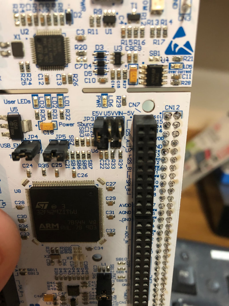
Now it's time to program your nucleo board. First thing to check before plugging it in is the supply voltage jumper. You can see here there's a 3x2 set of pins with E5V (external 5v), U5V (usb 5v) and VN-5V (not sure what this is for) above it. Move the jumper to U5V as shown here so the power is supplied by the usb cable. You will switch this to E5V later when connected to your machine.
First thing to do is download the ST Link software and follow all the instructions here: https://pin2dmd.com/installation/. Software here: https://www.st.com/en/development-tools/stsw-link004.html. Plug into the end shown here (opposite the ethernet end). I updated the unit's own firmware first, was version 18 or something when I plugged it in and version 26 was the latest I think. Update software is here: https://www.st.com/en/development-tools/stsw-link007.html. Download it, extract, make your way to the 'Windows' folder and double click the butterfly icon that says ST-LinkUpgrade. Click detect device, then update. Then you need to download the pin2dmd code and flash it to the Nucleo board. Pin2dmd software is the PIN2DMD.bin file here: https://github.com/lucky01/PIN2DMD/tree/master/firmware/latest/V4%20NUCLEO-144. In the ST Link software, click 'target' up at the top then 'program' and choose the location of the pin2dmd.bin file on your computer. It'll take a couple of seconds to upload the program, then you're done.
Switch the jumper on the Nucleo board to E5V now so it's powered from the shield.
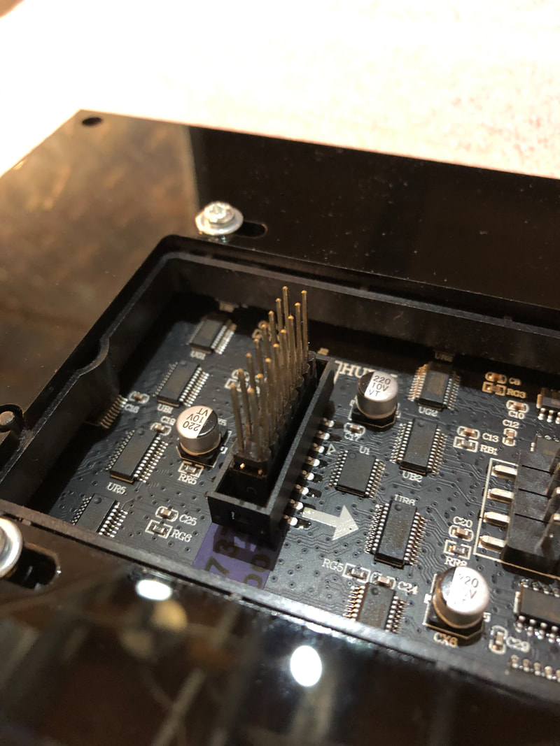
Once the Nucleo board is all programmed and soldered, plug it into the shield in the orientation shown here. It is now ready to be powered up.

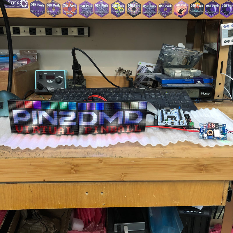
If you did everything right it'll look like this and a code will come up on the bottom of the display after about a minute of being powered on. You need to make a small donation, and send this code, your forum name and the forum you frequent to get a license key to activate the display. Link here, down at the bottom: https://pin2dmd.com/installation/. The file will be emailed to you within 24 hours. Rename the file you get to pin2dmd.key and copy and paste it to your micro SD card. insert the card in the waveshare slot on the shield and the next time you power it on it will be activated. This key file can also be used to register the editor software to colourize the files.

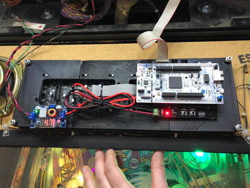
Now to install in your machine and power it all. This is a shot of where I got the power for mine. It's a WCS94 machine, and the suggested jacks on the power driver board were J116, J117 and J118 which all have 12vDC. Diagrams for this and other machines here: https://pin2dmd.com/hardware/. I found either of the top two worked well. Since they're all used for something already, you have to make an adapter splitting the wire and providing another pin header to plug the original plug in as well.
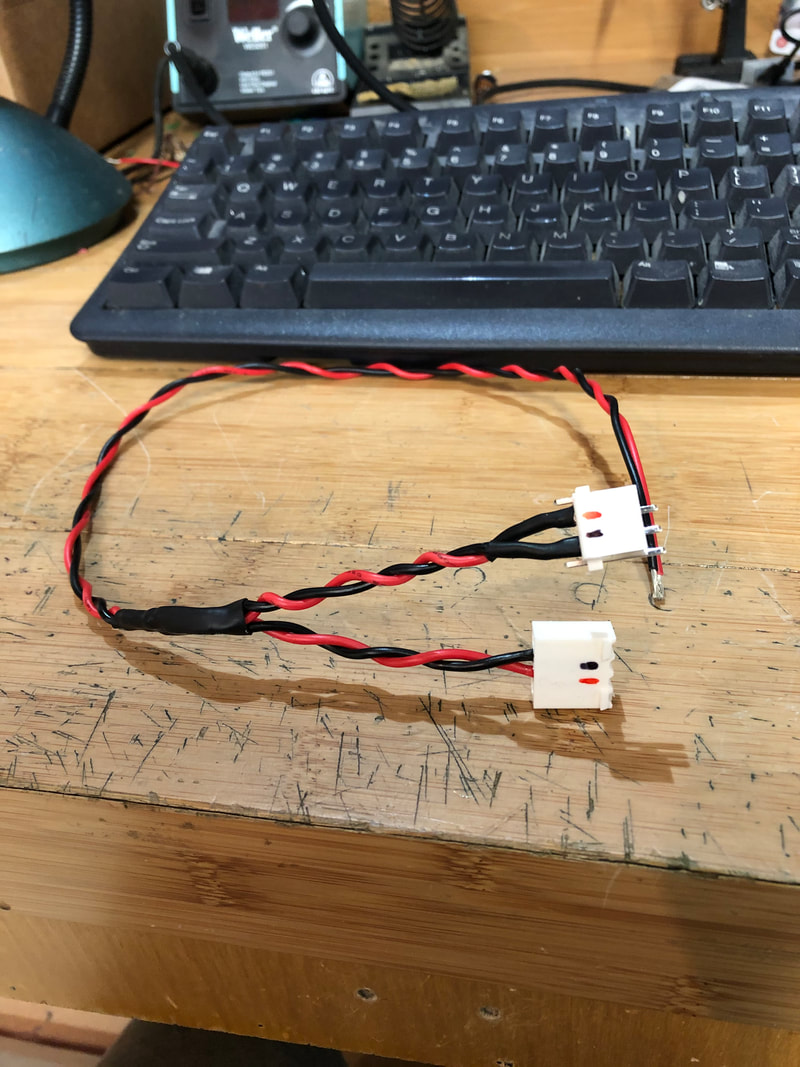
Here's a picture of the adapter I made. Took about 1-1.5' of 16-18g red and black wire and soldered another piece on each to split it and make a 'y'. Then one end got a 4 pin header and the other got crimp connector plug housing. I marked the red and black connections to avoid confusion when soldering. Heat shrink tubing on the split and pin header connections. 16g wire is hard to crimp connectors to so 18g wire may be better suited. The other end goes to the 'in' side of the power converter. Cut the one pin on the end off the header same as in the machine so it's 'keyed' properly for the plug and put a key pin in the same position on the plug as well (next to the red wire).

Last thing is to plug the idc connector from your pinball machine into the 'pinball' box header on the shield and fire up your machine. If you did everything correctly you'll have a super cool colour screen.
